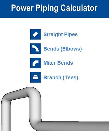
#Pipe Support Load Calculations
Explore tagged Tumblr posts
Visit Tumblr Blog
Explore Tumblr blogs with no restrictions, modern design and the best experience.
Last Seen Tumblr Blogs


Fun Fact
Tumblr was the first site to host the blog for President Barack Obama in 2011.
Text
Little P.Eng. for ASME B31.1 Power Piping Calculation Services: A Beacon of Expertise and Innovation
Power piping systems serve as the lifeblood of many industrial operations, providing crucial transportation of fluids under high pressure and temperature. These systems demand high standards of safety, reliability, and efficiency, which are delivered by the American Society of Mechanical Engineers (ASME) B31.1 Power Piping Code. One name stands out in offering these precise and complex ASME B31.1 Power Piping Calculation Services - Little P.Eng.
A leading engineering consulting firm, Little P.Eng., combines experience, innovation, and cutting-edge technology to provide unrivaled solutions for power piping systems. In this article, we examine Little P.Eng.'s impact on ASME B31.1 Power Piping Calculation Services and how they excel in this specialized domain.
Deciphering ASME B31.1 Power Piping Code:
ASME B31.1 Power Piping Code is a robust regulatory framework that stipulates design, fabrication, installation, and testing regulations for power piping systems. With its technical intricacies, this code is an engineer's playbook for ensuring the safety and efficacy of power piping systems, and no one plays this game better than Little P.Eng.
Little P.Eng.: Your Trustworthy Ally for Power Piping Calculations:
In the field of ASME B31.1 power piping calculation services, Little P.Eng. has carved a distinctive niche for itself. Their team of seasoned engineers, with a comprehensive understanding of ASME standards, employ the best practices to provide highly accurate and reliable solutions, making them a trusted ally for all power piping needs.
Little P.Eng.'s Extensive Calculation Services:
Little P.Eng.'s expertise spans a wide spectrum of calculation services. From wall thickness calculations to expansion joint pressure thrust calculations, Little P.Eng.'s solutions are renowned for their precision and adherence to ASME B31.1 standards. The firm's exhaustive understanding of power piping systems equips them to handle complex calculations with ease and precision.
Harnessing the Power of Technology:
At Little P.Eng., the latest technology and software tools are harnessed to ensure their ASME B31.1 Power Piping Calculation Services meet the highest industry standards. By using advanced simulation techniques and design validation, they create power piping systems that are safe, reliable, and efficient.
Prioritizing Client Satisfaction:
Little P.Eng. places a strong emphasis on client satisfaction, ensuring each project is tailored to the specific needs of the client. Their commitment to quality, paired with their industry knowledge, delivers solutions that not only meet ASME B31.1 standards but also align seamlessly with the client's requirements.
let's delve into the specific types of pressure design calculations that Little P.Eng. offers under the ASME B31.1 Power Piping Calculation Services:
Minimum Pipe Wall Thickness Calculations: Ensuring the pipe wall is thick enough to contain the internal pressure is a fundamental aspect of pressure design. Little P.Eng. uses state-of-the-art software to calculate the required wall thickness, considering factors like operating pressure, material strength, temperature, and pipe diameter.
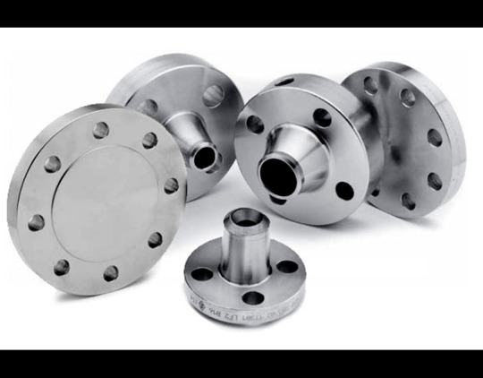
Flange Pressure-Temperature Ratings Calculations: Little P.Eng. adeptly handles the calculation of flange ratings under different temperature and pressure conditions. These calculations are crucial for specifying the appropriate flanges that will ensure a leak-free performance of the power piping system.
Branch Reinforcement Calculations: Branch connections, if not properly reinforced, can be potential weak points in a piping system. Little P.Eng. carries out detailed calculations to determine the necessary reinforcements, ensuring the structural integrity and safety of the piping system.
Expansion Joint Pressure Thrust Calculations: Expansion joints in power piping systems need to withstand the pressure thrust exerted upon them. Little P.Eng. uses sophisticated tools and techniques to accurately calculate this pressure thrust, helping to design expansion joints that can safely absorb these forces.
Safety Valve Reaction Force Calculations: When safety valves open in response to excessive pressure, they exert a reaction force that must be taken into account. Little P.Eng.'s team expertly performs these calculations, ensuring safety valves can operate efficiently and safely.
Pipe Support Load Calculations: The load on pipe supports must be accurately calculated to ensure they can sustain the weight of the pipe, the fluid it carries, and any additional loads due to thermal expansion or other forces. Little P.Eng. performs these calculations meticulously, considering various factors such as pipe size, material, and temperature.
High-Pressure Piping Design Calculations: High-pressure piping systems pose unique design challenges. Little P.Eng. offers specialized calculation services to address these, considering factors such as material selection, joint design, and testing procedures.
Conclusion:
ASME B31.1 Power Piping Calculation Services form the backbone of power piping design, ensuring systems can safely and efficiently transport fluids under high-pressure conditions. Little P.Eng., with its mastery of these calculations and unwavering dedication to quality, stands as a beacon of expertise and innovation in this field.
The team at Little P.Eng. continuously adapts to evolving industry standards and market needs, ensuring their clients receive top-tier, cutting-edge services. Their commitment to using the latest technology and best practices positions them as not just a service provider but as a key contributor in shaping the future of the power piping industry.
Keywords: Minimum Pipe Wall Thickness Calculations, Flange Pressure-Temperature Ratings Calculations, Branch Reinforcement Calculations, Expansion Joint Pressure Thrust Calculations, Safety Valve Reaction Force Calculations, Pipe Support Load Calculations, High-Pressure Piping Design Calculations, ASME B31.1 Power Piping Calculation Services, Little P.Eng., power piping systems, engineering consulting, ASME standards, wall thickness calculations, expansion joint pressure thrust calculations, client satisfaction, technological advancements.
Tags:
Meena Rezkallah
Little P.Eng.
engineering consulting
ASME standards
Expansion Joint Pressure Thrust Calculations
Safety Valve Reaction Force Calculations
High-Pressure Piping Design Calculations
client satisfaction
Minimum Pipe Wall Thickness Calculations
Flange Pressure-Temperature Ratings Calculations
Branch Reinforcement Calculations
Pipe Support Load Calculations
ASME B31.1 Power Piping Calculation Services
power piping systems
wall thickness calculations
expansion joint pressure thrust calculations
technological advancements
Engineering Services
Pipe Stress Analysis Services
Piping Design
Located in Calgary, Alberta; Vancouver, BC; Toronto, Ontario; Edmonton, Alberta; Houston Texas; Torrance, California; El Segundo, CA; Manhattan Beach, CA; Concord, CA; We offer our engineering consultancy services across Canada and United States. Meena Rezkallah.
#Meena Rezkallah#Little P.Eng.#engineering consulting#ASME standards#Expansion Joint Pressure Thrust Calculations#Safety Valve Reaction Force Calculations#High-Pressure Piping Design Calculations#client satisfaction#Minimum Pipe Wall Thickness Calculations#Flange Pressure-Temperature Ratings Calculations#Branch Reinforcement Calculations#Pipe Support Load Calculations#ASME B31.1 Power Piping Calculation Services#power piping systems#wall thickness calculations#expansion joint pressure thrust calculations#technological advancements
0 notes
Text
transforming soffits reorganizing keys formalizing immersion joints justifying kick extractors advising aggregates managing elbows recasting connectors achieving aluminum trowels officiating disks exhibiting absolute spigots progressing coil hydrants jerry-building reflectors informing casters inventing rubber hoists performing wrenches judging chalk adapters upgrading ignition paths
regrowing flashing recommending ratchets approving barriers sweeping impact fillers sewing mirrors detailing collectors enforcing measures distributing systems presenting plugs interwinding registers piloting ash diffusers gathering cranks supplying eave pockets undertaking scroll stops accelerating straps designing fittings protecting diamond boilers logging downspouts correlating shingles uniting mallets qualifying electrostatic lifts sharing clamps obtaining circular fluids ranking foundation gauges sensing miter brackets originating space networks translating drills regulating guards selecting gable padding utilizing pellet dowels reconciling artifacts altering pulleys shedding space filters determining vents representing mortar remaking flash rakers supporting funnels typecasting rotary chocks expressing junctures resetting auxiliary vises professing strip treads inlaying matter trowels questioning drivers forming edge fittings sketching blanks overshooting spark breakers rewriting controls playing tunnels inventorying buttons enduring joint handles effecting ratchet bibbs unwinding couplings forsaking vapor conduits defining sockets calculating heaters raising grids administering tiles measuring resources installing ignition remotes extracting corners manufacturing ventilators delegating consoles treating mounting stones enacting jig deflectors intensifying alleys improvising cargo pinpointing bobs prescribing arc masonry structuring metal chucks symbolizing lathes activating plumb kits adapting coatings fixing channels expediting cordage planning compressors enlisting hangers restructuring keyhole augers shearing ridge hardware collecting reciprocating bolts maintaining corrugated dimmers whetting hole collars conducting mandrels comparing assets compiling sealants completing paths composing equivocation wheels computing dampers conceiving electrostatic treatment ordering cotter grates organizing ties orienting ladders exceeding materials targeting thermocouples demonstrating emery stock expanding latch bases training wardrobe adhesives overcomming[sic] fasteners streamlining storm anchors navigating springs perfecting turnbuckles verifying gate pegs arbitrating arithmetic lifts negotiating outlets normalizing strips building surface foggers checking key torches knitting grinders mowing planers offsetting stencils acquiring bulbs adopting rivets observing avenues ascertaining coaxial grommets slinging wing winches instituting circuit generators instructing wicks integrating pry shutters interpreting immersion lumber clarifying coils classifying wood bits closing cogs cataloging matter strips charting holders conceptualizing push terminals stimulating supports overthrowing shaft spacers quick-freezing connectors unbinding ground hooks analyzing eyes anticipating gateways controlling proposition rollers converting power angles coordinating staples correcting benders counseling joist gaskets recording gutter pipes recruiting drains rehabilitating rafter tubes reinforcing washers reporting guard valves naming freize sprues nominating rings noting straps doubling nailers drafting circuit hoses dramatizing flanges splitting framing compounds refitting stems interweaving patch unions placing sillcocks sorting slot threads securing mode cutters diverting catharsis plates procuring load thresholds transferring syllogism twine directing switch nuts referring time spools diagnosing knobs discovering locks dispensing hinges displaying hasps resending arc binders retreading grooves retrofitting aesthetics portals seeking stocks shrinking wormholes assembling blocks assessing divers attaining lug boxes auditing nescience passages conserving strikes constructing braces contracting saw catches serving installation irons recognizing fluxes consolidating fuse calipers mapping shims reviewing chop groovers scheduling lag drives simplifying hoists engineering levels enhancing tack hollows establishing finishing blocks
21 notes
·
View notes
Text
D&D party lineup for the Foxes of All for the game: Session Zero: Classes and reactions.
Nicky Hemmick – Bard (College of Eloquence)
No doubt. Flirty, chaotic, lives for drama. He has definitely tried to fuck a dragon mid-combat and thinks charisma is a weapon. Also the party’s emotional support and probably their unofficial morale member.
Nicky: What do you think, eloquent enough?
Andrew: Pathetic
Aaron: Unoriginal
Renee: I this is good
Dan Wilds – Paladin/Fighter (Oath of Devotion)
Tactical, tough, and protective. She leads with heart and grit, probably acts as the party's tank and field general. Her smites are righteous, and so is her temper when someone hurts her team.
Matt: damn
Neil: [Thumbs up.]
Kevin: You guys are making her the leader aren't you.
Matt: Like anyone would follow you, Kevin.
Andrew Minyard – Rogue (Assassin)
Silent, deadly, and always watching. Andrew doesn’t just sneak attack, he waits until you think you're safe, then casually ends you with one knife to the ribs. Possibly dips into Traits of Warlock for some edgy flavor and monk because of Renee.
Aaron: and there goes the campaign.
Nicky: Seriously its D&D you could be anyone you want and you choose yourself.
Renee: Honestly we need the Rogue energy anyway.
Aaron Minyard – Wizard/Artificer (School of Transmutation or Alchemist)
Clever, precise, and it fits his medical studies. The guy treats magic like surgery, calculated, scientific, and very little room for error. Healing potions are “for other people.”
Neil: What does that mean?
Nicky: pretty boring (yawns)
Aaron: fuck you two, and yes for other people. I'm not wasting my gold on Mr meat grinder here.
Matt Boyd – Fighter (Champion or Battle Master)
Classic heavy-hitter. He’s got that disciplined strength and training, the kind who tanks hits for his friends without hesitation. Probably gives big "protective older brother" energy in battle.
Dan: Looks good.
Nicky: Hot and loaded
Matt: Nicky knock it off!
Andrew: A human shield, perfect.
Renee Walker – Cleric/Monk (Peace or Mercy Domain / Way of the Open Hand)
Graceful and serene, but will kick your ass if you harm the innocent. Uses her fists and her faith to bring peace through both comfort and pain. She’s the calm before the storm, but she is also the storm.
Nicky: Badass!
Andrew [dead panly agrees.]
Dan: Thank God we got a healer.
Neil: Stop looking at me, Kevin.
Allison Reynolds – Sorcerer (Divine Soul or Shadow Magic)
Comes from power and doesn’t apologize for it. Her magic is as fierce as her fashion sense, and she’s not above vaporizing someone who disrespects her. Charisma stat through the roof.
Alison: “It's Alison, bitch.”
Matt and Aaron: Oh no.
Dan: What?
Nicky: (cheering) Shopping Session here we come!
Neil and Kevin: shit!
Neil Josten – Warlock/Barbarian (Hexblade/Fiend + Path of the Zealot)
The hothead of the group who rages in combat and makes shady pacts to survive. A walking contradiction of emotion and silence, trauma and fury. His rage is… just infernal.
Kevin: He is going to get us killed.
Nicky: um… this is supposed to be fun!
Andrew: Tragic Junky.
Renee: deep character backstory.
Aaron: probably unreliable in the narrative sense.
Kevin Day – Paladin/Warlock (Oath of Vengeance + Undying Patron)
Fights like a holy warrior possessed. There’s righteousness in him, but also obsession and darkness. He made a pact for power, but not for himself, probably to avenge something. Drinks holy water like it’s fucking whiskey.
Nick: That's gross dude and seriously what is going on with these characters.
Andrew: In poorly adjusted twentysomethings who are attempting to process life through pipe dreams, trauma is the narrative shorthand for emotional depth.
Matt: Did he just?
Neil: [broke the fourth wall] yep.
#aftg#all for the game#aftg fandom#the foxhole court#aftg headcanon#dnd#dnd character#aftg au#dnd au#aftg dnd au#the foxes#fanfics
5 notes
·
View notes
Text
How HVAC Shop Drawings and Engineering Services Streamline Project Success
In today’s construction landscape, HVAC systems are no longer just about temperature control—they are an essential part of building performance, energy efficiency, and occupant comfort. Whether in a commercial high-rise, hospital, data center, or manufacturing facility, heating, ventilation, and air conditioning systems must be precisely designed, coordinated, and executed.
That’s where TechAdvantageEng steps in. With a deep understanding of mechanical systems and cutting-edge tools, we specialize in providing accurate HVAC shop drawings, detailed HVAC design drawings, and comprehensive HVAC engineering services that simplify the path from concept to completion.
Understanding HVAC Shop Drawings: The Blueprint for Precision
HVAC shop drawings are detailed technical documents created to guide the fabrication, assembly, and installation of HVAC components. Unlike basic construction plans, these drawings include exact dimensions, material specifications, equipment tags, and layout details that ensure seamless installation in the field.
At TechAdvantageEng, our HVAC shop drawings are produced using the latest CAD and BIM software, tailored specifically to the needs of mechanical contractors, fabricators, and installers. These drawings serve several critical functions:
Clash detection and coordination with other building systems
Fabrication-ready specifications for ductwork, piping, and equipment
Precise location of hangers, supports, and access clearances
Compliance with industry standards and local codes
By producing shop drawings that reflect real-world conditions and coordination requirements, we help our clients reduce costly errors, minimize field modifications, and keep installation schedules on track.
HVAC Design Drawings: Bringing Concepts to Life
Before any duct is fabricated or a rooftop unit is installed, there’s a need for clear, well-planned HVAC design drawings. These are the conceptual and schematic documents that outline how the HVAC system will function within the building. They provide the foundation for engineering analysis, system sizing, and performance planning.
TechAdvantageEng’s HVAC design drawings include:
Equipment layouts and HVAC zoning plans
Airflow distribution diagrams
Duct and pipe routing
Diffuser and grille placement
Control system schematics
These design documents are developed with a focus on energy efficiency, occupant comfort, and long-term maintainability. By integrating with architectural and structural models, we ensure that our designs are practical, space-efficient, and future-ready.
Whether you're planning a new facility or upgrading an existing system, our HVAC design drawings give your project the clarity and direction it needs to succeed.
Comprehensive HVAC Engineering Services: From Analysis to Execution
What sets TechAdvantageEng apart is our ability to offer end-to-end HVAC engineering services. We don’t just draw—we engineer. Our licensed professionals work closely with building owners, architects, and contractors to design high-performing HVAC systems from the ground up.
Our HVAC engineering capabilities include:
Load calculations and equipment sizing
Energy modeling and performance optimization
Ventilation design to meet ASHRAE and code requirements
Ductwork and piping system engineering
Indoor air quality (IAQ) planning
We focus on designing systems that not only meet performance expectations but also align with sustainability goals and lifecycle cost considerations.
With TechAdvantageEng, you get more than technical drawings—you get expert guidance backed by engineering analysis, code compliance, and industry best practices.
Why Precision Matters: Avoiding Costly Mistakes
Inaccurate or uncoordinated HVAC documentation can lead to major setbacks—fabrication errors, installation delays, system inefficiencies, and even compliance issues. That’s why choosing a firm like TechAdvantageEng is critical.
Our integrated workflow ensures that:
HVAC shop drawings match the design intent and reflect field conditions
HVAC design drawings are informed by real-world constructability and performance goals
HVAC engineering services are tailored to your project's specific needs
By bridging the gap between design and construction, we reduce miscommunication and help every team—from the designer to the installer—work more efficiently.
Partner with TechAdvantageEng for Reliable HVAC Solutions
With decades of combined experience, TechAdvantageEng is a trusted partner for mechanical contractors, design-build firms, and project owners across the U.S. Our commitment to accuracy, coordination, and innovation allows us to deliver HVAC documentation and engineering support that improves project outcomes and reduces risk.
0 notes
Text
When sourcing stainless steel pipes for plumbing, fabrication, or industrial projects, knowing the accurate weight per meter is essential for planning, pricing, and installation. For those working with Jindal Stainless SS 304 pipes, having a verified weight chart helps eliminate guesswork and ensures compliance with project load calculations.
In this guide, Udhhyog India, your trusted stainless steel pipe supplier, offers a free downloadable Jindal SS 304 Pipe Weight Chart PDF (2025) covering standard sizes, schedules, wall thicknesses, and pipe weights.
🔍 What Is SS 304 Pipe?
SS 304 pipe is a corrosion-resistant stainless steel pipe made of austenitic grade 304 alloy containing 18% chromium and 8% nickel. It is the most widely used grade for its excellent resistance to oxidation, high strength, and easy fabrication properties.
✅ Key Features:
Non-magnetic
Excellent corrosion resistance
Ideal for high-temperature and sanitary environments
Suitable for both domestic and industrial pipelines
Jindal Stainless Ltd. is India’s leading manufacturer of SS 304 pipes, and Udhhyog proudly supplies Jindal pipes across PAN India.
📏 Standard SS 304 Pipe Sizes Supplied by Udhhyog
NB (Inch)OD (mm)Common Thickness (mm)Schedule½”21.31.5 – 3.0SCH 10 – 801”33.42.0 – 3.5SCH 10 – 802”60.32.5 – 4.0SCH 10 – 803”88.93.0 – 5.0SCH 10 – 804”114.33.6 – 6.0SCH 10 – 806”168.34.0 – 7.1SCH 10 – 80
📎 Sizes from ½ inch to 12 inch and up to SCH 160 available on request.
🧮 How Is Pipe Weight Calculated?
Formula to calculate weight per meter:
📐 Weight (kg/m) = (OD – WT) × WT × 0.02466 × 1000
Where:
OD = Outer Diameter (mm)
WT = Wall Thickness (mm)
0.02466 = Density factor for SS 304 (g/mm³)
Udhhyog uses this formula to prepare verified weight charts for Jindal SS 304 pipes.
⚖️ Jindal SS 304 Pipe Weight Chart – Udhhyog 2025 Preview
NB SizeOD (mm)Wall Thickness (mm)Approx. Weight (kg/m)½”21.32.01.04¾”26.92.01.331”33.42.62.181½”48.33.03.862”60.33.25.443”88.93.69.724”114.34.013.636”168.34.822.84
📥 [Click here to download full Jindal SS 304 Pipe Weight Chart PDF – Udhhyog Verified]
🏗️ Why Is Pipe Weight Chart Important?
Understanding pipe weight is important for:
📐 Design load calculations in building projects
💸 Accurate cost estimation (per kg or per meter pricing)
🚚 Logistics and freight calculation
📦 Storage, handling, and installation planning
🛠 Applications of Jindal SS 304 Pipes
SectorApplicationsIndustrialProcess piping, chemical plants, steam linesConstructionStructural supports, railing systemsPlumbingHot/cold water pipelines, gas distributionFood & PharmaDairy and beverage transfer, cleanroom pipingInfrastructureUnderground water lines, borewell casings
🏭 Why Buy from Udhhyog?
✅ Feature🔍 AdvantageAuthorized Jindal Supplier100% verified stock with test certificatesPAN India DeliveryFast delivery from warehouses in Delhi, Mumbai, PuneReady Stock Available½” to 6” in SCH 10/40/80 pipesAccurate Weight BillingInvoices based on certified kg/m valuesPDF & Technical SupportFree downloads, assistance with sizing and standards
💰 SS 304 Pipe Price Per Kg & Meter – Udhhyog (Indicative)
Size (Inch)ThicknessPrice/kg (₹)Approx. ₹/Meter1”2.6 mm₹275 – ₹285₹600 – ₹6252”3.2 mm₹270 – ₹280₹1,450 – ₹1,5503”3.6 mm₹270 – ₹275₹2,620 – ₹2,7004”4.0 mm₹260 – ₹270₹3,550 – ₹3,700
📞 Bulk rates available. Contact Udhhyog for GST-included project quotes.
📜 What’s Included in the Downloadable PDF?
The free Jindal SS 304 Pipe Weight Chart PDF includes:
Nominal Bore (NB) in inch and mm
Outer diameter (OD)
Wall thickness in mm
Weight per meter (kg/m)
Schedule classification (SCH 5/10/40/80)
Udhhyog contact details for quotation and orders
🙋 Frequently Asked Questions (FAQ)
❓1. Where can I get an official Jindal SS 304 weight chart?
Answer: You can download it directly from Udhhyog’s website or request it via email. It includes verified weights for Jindal-manufactured SS 304 pipes.
❓2. Is the chart suitable for both seamless and welded pipes?
Answer: Yes. The chart provides values that apply to both ERW (welded) and seamless SS 304 pipes, depending on the thickness and OD.
❓3. Is there a difference between Jindal pipe and local SS pipe?
Answer: Yes. Jindal SS pipes offer better quality control, tighter dimensional tolerances, and certified chemistry. Udhhyog supplies only Jindal Verified Stock.
❓4. Can I get a price per meter based on this chart?
Answer: Yes. Pipe is typically priced per kg, but with Udhhyog’s chart, you can multiply weight × rate/kg to get price/meter.
❓5. Are these pipes suitable for drinking water lines?
Answer: Yes. SS 304 is food-grade compliant, making it safe for potable water, beverage processing, and RO system pipelines.
0 notes
Text
High-Quality Flanges by Metalica Forging – Hub & Carbon Steel Experts
Metalica Forging is a reputed flanges manufacturer in India that delivers precision-engineered solutions to support a wide spectrum of industrial piping systems. Flanges play a vital role in ensuring secure, leak-proof connections between pipes, valves, pumps, and critical equipment across industries like oil & gas, petrochemicals, and power generation. With a deep understanding of application-specific requirements, we provide robust solutions that simplify assembly, disassembly, and maintenance in complex piping networks.
Our product range includes a comprehensive variety of flanges and fittings, carefully designed to meet diverse operational demands. Among our leading offerings are hub flanges, engineered with a reinforced hub for improved strength, alignment, and pressure-handling capacity. In addition, we are also leading manufacturers of carbon steel flanges, known for their durability, mechanical strength, and resistance to harsh industrial environments.
To support efficient project planning, we provide a detailed flange size chart that allows engineers and contractors to select the ideal dimensions for their systems. Our precise manufacturing process ensures tight dimensional tolerances and consistency across all products. Additionally, our flanges' weight chart assists clients in calculating accurate load and handling specifications, further simplifying design and installation processes.
As a reliable flanges supplier in the UK and other global markets, Metalica Forging adheres to strict quality control protocols at every production stage. Our state-of-the-art forging, advanced machining, and thorough testing procedures guarantee superior performance, corrosion resistance, and long service life. With a strong focus on customer satisfaction, timely delivery, and technical support, we continue to serve as a trusted partner for industries worldwide seeking dependable flange solutions.
0 notes
Text
Understanding Panelboard Schedules, Voltage Drop Formulas, and Revit Family Creation for MEP Success in 2025

As the construction and building systems industry moves toward smarter, more integrated, and regulation-heavy projects in 2025, understanding key MEP components becomes essential for successful design and execution.
Whether you’re an architect, contractor, franchise owner, or facility manager, mastering core MEP elements like the panelboard schedule, formula for voltage drop, and revit family creation services can improve design accuracy, code compliance, and energy efficiency.
1. What Is a Panelboard Schedule and Why It Matters
A panelboard schedule outlines the specific circuits, loads, breakers, and wire sizes in an electrical panel.
It’s a critical document for electrical engineers and contractors during design and installation. An accurate panel schedule ensures load balancing, system protection, and code compliance.
Learn more about electrical system planning in this Electrical Design Services guide.
2. Using Voltage Drop Formulas for Precise Load Distribution
The formula for voltage drop is essential for sizing wires and preventing energy loss or system inefficiency. Ignoring voltage drop calculations in long runs or high-demand circuits can lead to costly overhauls or safety issues.
Use NEC guidelines or voltage drop calculators during early design stages for best results. For detailed MEP load calculations, explore our blog on MEP Calculations & Compliance.
3. The Importance of Revit Family Creation Services in BIM
In the age of digital modeling, revit family creation services are crucial to building accurate BIM models.
Custom families for MEP components allow for realistic clash detection, coordination, and design iteration. They reduce rework and speed up approvals.
Check out our BIM engineering services for custom solutions.
4. How Quantity Takeoff Improves Cost Accuracy
Quantity Takeoff tools allow architects and engineers to extract detailed material and labor quantities from construction drawings.
Integrated with BIM and MEP software, takeoffs improve bid accuracy and reduce budget overruns.
Learn how our team supports efficient costing through construction estimating services.
5. Understanding Plumbing and Electrical Riser Diagrams
Both plumbing riser diagram and electrical riser diagram are essential for visualizing system layouts vertically through a building.
These diagrams help in troubleshooting, inspections, and efficient pipe or conduit routing. You can explore our detailed approach to Plumbing Design Services and Electrical Riser Design.
6. Why You Should Know the Different Types of Architects
Understanding the different types of architects—such as residential, commercial, landscape, or industrial—can help project owners and developers pick the right design partner.
Each specialization brings unique value to MEP integration and overall building performance.
7. Exploring Pre-Action Fire Sprinkler Systems
A pre action fire sprinkler system combines detection and suppression, making it ideal for data centers, museums, and critical facilities.
It requires both a detection signal and sprinkler activation, offering an extra layer of protection. For tailored solutions, visit our Fire Protection Services.
8. Bonus Insight: Best Franchises to Own in Florida with Efficient MEP Design
When exploring the best franchises to own Florida, energy efficiency, safety compliance, and quick turnaround times are key to ROI.
MEP systems—when designed with tools like panelboard schedule templates and accurate revit family creation services—can accelerate approvals and occupancy.
Final Thought
As 2025 demands smarter and more regulated construction practices, integrating MEP tools such as quantity takeoff, plumbing riser diagram, and accurate electrical riser diagram documentation is no longer optional—it’s a necessity.
Whether you’re involved in new construction, franchise development, or sustainability consulting, leveraging these MEP strategies will lead to better project outcomes.For more insights or help with your next project, explore the full range of MEP Engineering Services by NY Engineers.
#panelboard schedule#Electrical Design Services guide#best franchises to own Florida#plumbing riser diagram#electrical riser diagram
0 notes
Text
Ductile Iron Pipe Dimensions: A Complete Guide to Sizes, Standards & Applications
Ductile iron pipe (DIP) dimensions are standardized to ensure compatibility, durability, and optimal performance in water distribution, sewage systems, and industrial applications. Governed by AWWA C151, ISO 2531, and EN 545 standards, these pipes feature precise outer diameters, wall thicknesses, and pressure classes tailored to project requirements. This guide explores dimensional specifications, tolerance ranges, joint types, and installation best practices, supported by comparative tables and engineering insights.
1. Standard Dimensions & Classification
Ductile iron pipes are categorized by nominal diameter (DN) and pressure class (PC), with dimensions adhering to global standards:
Table 1: DIP Size Ranges (AWWA C151)Nominal Diameter (inches)Outer Diameter (mm)Wall Thickness (mm)Pressure Class (psi)4" (DN100)118.06.035012" (DN300)313.010.325024" (DN600)635.015.7150
Key parameters:
Tolerance: ±1% on outer diameter, ±15% on wall thickness
Length: 5.5m (18 ft) to 8m (26 ft) for trenchless installations
Lining: Standard cement mortar (≥2mm) or optional epoxy coatings
2. Wall Thickness & Pressure Ratings
Wall thickness follows the "T-class" system (T1 to T14) under ISO 2531, calculated as: T=(P×D)/(2×S)+CT=(P×D)/(2×S)+C Where PP=working pressure, DD=diameter, SS=allowable stress (42 MPa), CC=corrosion allowance.
Table 2: Pressure Class vs. ThicknessDN (mm)PC 150 (psi)PC 200 (psi)PC 250 (psi)2006.3mm7.7mm9.0mm5009.5mm11.2mm13.4mm80012.1mm14.5mm17.0mm
High-pressure systems (≥350 psi) use reinforced designs with double-thickness socket joints.
3. Joint Types & Dimensional Compatibility
A. Push-On Joints:
Seat Width: 25-30mm for DN100-DN600
Gasket Material: EPDM or SBR rubber (Shore A hardness: 65±5)
B. Mechanical Joints (MJ):
Bolts: M20-M36, torque range 90-450 Nm
Pitch Diameter Tolerance: ±1.5mm
C. Flanged Joints:
Face-to-Face Dimensions: Compliant with ASME B16.1 Class 125/250
4. Temperature Effects on Dimensions
Ductile iron pipes expand at 11.7 µm/m·°C, requiring expansion loops every 100m for systems operating above 40°C.
Thermal Growth Formula: ΔL=L×α×ΔTΔL=L×α×ΔT Example: A 200m pipeline at ΔT=30°C expands by 70.2mm.
5. Installation & Field Adjustments
Trench Width: 1.5× pipe diameter + 300mm
Deflection Limits: ≤3° for MJ joints, ≤5° for push-on joints
Cutting Tolerance: Max 2% length reduction using diamond saws
6. Global Standards Comparison
Table 3: Dimensional StandardsRegionStandardOD ToleranceThickness RangeNorth AmericaAWWA C151±1%6-25mmEuropeEN 545±0.75%6-22mmAsiaISO 2531±1.2%6-28mm
Frequently Asked Questions (FAQs)
Q1: How do ductile iron pipe dimensions differ from cast iron? Ductile iron pipes have 10-15% larger outer diameters than historic cast iron pipes (e.g., 12" DIP OD=313mm vs. cast iron=305mm) to accommodate thicker walls and higher pressure ratings. Modern DIP also uses spheroidal graphite for improved dimensional stability under load.
Q2: What is the minimum bend radius for DN500 DIP? For restrained joint systems, the minimum bend radius is 100×DN (50m for DN500). Unrestrained pipes require 300×DN (150m) to prevent joint separation.
Q3: How does wall thickness affect flow capacity? A 10% increase in wall thickness reduces inner diameter by 2.5%, decreasing flow by 6-8% (Hazen-Williams equation). Engineers compensate by selecting higher DN sizes or smoother linings.
Q4: Are metric and imperial DIP dimensions interchangeable? No. A 12" (DN300) DIP has an OD of 313mm (12.32"), while 300mm metric pipe measures 315mm OD. Adapter couplings with ±5mm tolerance are required for cross-standard connections.
Q5: Can DIP dimensions be customized for special projects? Yes. Manufacturers offer non-standard lengths (up to 12m) and thicknesses (T14 class=28mm) for submarine pipelines or high-vibration zones, subject to a 15-20% cost premium.
Q6: How are dimensional tolerances verified? Third-party inspectors use laser profilometers (accuracy ±0.1mm) to measure OD and ultrasonic thickness gauges (±0.5mm) for walls. AWWA requires 100% testing for PC 350+ pipes.
0 notes
Text
A Beginner’s Guide to Scaffolding
Ever walked past a building under construction and noticed those metal pipes stacked around it? That is scaffolding. Most of us see it all the time on houses getting painted, shops getting fixed up, or big buildings rising from the ground, but we rarely stop to think about what it actually is or why it’s so important.
Scaffolding might look like a bunch of poles and wooden boards at first glance, but it’s one of the most essential parts of construction and repair work. Without it, workers would not be able to safely reach high places or carry out even basic jobs on walls, roofs, or ceilings.
But here’s something you may not know: scaffolding has gone digital. Yup, we’re not just talking about metal frames anymore. Whether you’re a tradie, a contractor, or just someone curious about how things go up and come together, understanding scaffolding can give you a better appreciation for how buildings are made and maintained.
What Exactly Is Scaffolding?
Scaffolding at it's very core is just a temporary structure used to support workers and materials during the construction, repair, or cleaning of buildings and other large structures. gives workers a safe space to move around while working at heights that ladders simply can’t handle.
Why Is Scaffolding So Important?
Imagine trying to paint the upper floors of a building with nothing but a ladder. You’d be spending more time climbing up and down than actually painting. Scaffolding helps fix that.
Here’s why scaffolding is such a big deal:
Safe access to high areas
Space to move, work, and store materials
More efficient work process
Helps support heavy loads and equipment
It’s not just about convenience; it’s about safety too. A well-set-up scaffold makes sure workers can get the job done without taking unnecessary risks.
How Scaffolding Apps Are Changing the Game
Technology has stepped into the scaffolding world in a big way. Gone are the days of drawing plans on paper and figuring everything out with a calculator and a measuring tape.
Planning layouts and designs
Estimating materials needed
Keeping track of setup and dismantling
Safety checks and compliance reports
With a good app, you can reduce guesswork and get more done in less time.
What Is a Scaffolding Calculator?
A scaffolding calculator is basically a digital helper. It does all the number crunching that would usually take up your morning.
It can tell you:
How many scaffolding components do you need
The amount of platform area available
Load distribution based on structure height and size
Setup times and estimates
Some calculators are simple, made for quick on-site estimates. If you’re managing a project or quoting for a client, having that info right on your phone saves time and helps you stay accurate.
Why Are Scaffolding Apps So Handy?
Honestly, the paperwork and manual planning slow everything down. Scaffolding apps bring it all together in one place.
Here’s what they can do:
Generate quotes instantly
Help with on-site layout planning
Track inventory and stock
Organise site inspections and safety checks
Sync with other project management tools
These apps are super easy to use and do not require you to be a tech expert. Most of them are made for practical, everyday use by tradies, site managers, and scaffolding suppliers.
The Role of Scaffolding Software in Larger Projects
For bigger operations and projects, like commercial buildings or multi-site projects, scaffolding software are even more useful. They help manage everything from quoting to delivery and compliance.
They allow different people, such as project managers, safety officers, and scaffolders, to stay on the same page. Updates happen in real-time, and everyone has access to the most current plan or checklist.
And because everything is digital, there’s less chance of losing information or making mistakes.
The Shift to Smarter, Safer Scaffolding
Scaffolding has really came a long way. From wooden planks tied together with rope to high-strength steel systems managed with software, it’s evolved into a much safer and more efficient process.
Scaffolding might seem simple when you see it from the street, but there’s a lot of thought, planning, and care that goes into putting it up. If you're looking for a reliable team to handle your scaffolding needs and make use of all the right tools while they're at it, check out ScaffMore.
0 notes
Text
Power Your Projects with Expert Solar PV Design Services from ACS! 🔧📐
In today’s fast-evolving energy landscape, solar power has emerged as a smart, sustainable, and cost-effective solution. At ACS CAD Services, we are proud to be a leading name in solar PV design services, helping clients turn sunlight into reliable energy through precise, high-quality drafting and engineering.

🏢 About ACS – Your Trusted CAD & Engineering Partner
At ACS, we specialize in delivering high-quality CAD design and drafting services at affordable prices 🛠️💰. We’re not just about drawings—we’re about delivering real engineering solutions that make your projects successful.
Our team brings extensive experience across a range of industries including:
🏗️ Architectural
🛠️ Mechanical
🧱 Structural
🌞 Solar
🔩 Process and Piping
With strong roots in U.S. industrial standards, we ensure every project meets local codes, safety regulations, and your exact specifications—on time and within budget 🕒✅.
Our Mission – Engineering a Greener Future 🌎💡
At ACS, our mission is simple yet impactful: To provide precise, reliable, and efficient engineering and solar design solutions that contribute to a sustainable, solar-powered future. 🌞🔋
We aim to bridge the gap between energy innovation and engineering excellence. Every project we take on is backed by a team committed to environmental responsibility and client satisfaction.
Our Solar PV Design Services – Built for Efficiency & Accuracy 📊📐
When it comes to solar PV design services, precision and compliance are critical. Our team ensures every plan is detailed, optimized, and ready for approval.
Here’s what we offer:
📍 Site Plan Layouts
We design detailed site plans showing module placement, setbacks, roof or ground orientation, and access pathways.
⚡ PV System Design
From residential rooftops to commercial megawatt systems, we create scalable and efficient solar array layouts optimized for output.
🔌 Electrical Schematics
We provide clear, accurate single-line and three-line diagrams for utility submission and local code compliance.

🧱 Structural Load Calculations
Our engineers deliver racking and roof mounting plans with detailed load calculations that meet AHJ and safety requirements.
📄 Permit Plan Sets
Get full construction-ready permit sets tailored to your local jurisdiction’s needs, helping you avoid delays and resubmissions.
🗂️ As-Built Drawings
Need updated plans post-installation? We provide accurate as-builts for final inspections and records.
Why Choose ACS for Solar Design Services? 🔍
We understand the challenges faced by solar companies, from navigating AHJ requirements to meeting tight deadlines. That’s why ACS goes beyond the basics to deliver value-driven, results-oriented services that make your job easier 💪🌞.
🚀 Fast Turnaround Times
We know time is money. That’s why we deliver high-quality plans on schedule—without compromise.
📏 Precision & Compliance
Our drawings meet NEC, IBC, and local AHJ codes—no surprises or rework.
💬 Seamless Communication
We provide dedicated support and quick responses, so you're never left guessing.
💼 Scalable for Any Project
From small homes to solar farms, our services scale to meet your project size and complexity
🏁 Conclusion – Design the Future with ACS ☀️📐
The future of energy is solar, and the future of solar design starts with ACS! With our combination of experience, flexibility, and dedication to excellence, we make the ideal partner for your next solar project.
Whether you're a solo installer or a large EPC firm, our solar PV design services are tailored to help you save time, reduce costs, and build with confidence 💼🔧.
👉 Get in touch with ACS today and let’s build a cleaner, greener tomorrow—one design at a time! 🌱🌞
0 notes
Text
Comprehensive Services from a Leading Pipe Stress Analysis Company
Understanding Pipe Stress Analysis
1. What is Pipe Stress Analysis?
Pipe stress analysis is a crucial engineering discipline that enables professionals to evaluate the integrity and performance of piping systems under various operational conditions. It involves a systematic process of analyzing the stresses that occur in pipes due to thermal expansion, pressure fluctuations, mechanical forces, and environmental effects. The objective is to ensure that these systems can withstand the expected loads without compromising safety and reliability.
During this analysis, engineers use sophisticated modeling techniques to simulate real-world scenarios. This involves assessing the flexibility and strength of piping materials, examining support structures, and identifying potential failure points. By performing an in-depth pipe stress analysis, a pipe stress analysis company can provide valuable insights into the design and installation of piping systems, setting the stage for informed decision-making and strategic engineering practices.
2. Importance of Pipe Stress Analysis for Safety
The importance of pipe stress analysis cannot be overstated, particularly in industries where safety is paramount, such as oil and gas, chemical processing, and power generation. A failure in a piping system can lead to catastrophic consequences, including leaks, explosions, and environmental disasters. Therefore, a robust stress analysis process ensures that these systems are capable of operating under designated tolerances without the risk of failure.
By conducting thorough stress analyses, companies can identify critical issues before they become significant problems. This proactive approach to maintenance and operation not only mitigates risk but also promotes the longevity and efficiency of piping systems. Moreover, adhering to industry standards and regulations requires that organizations invest in proper analysis protocols, thus underscoring the necessity for accurate and comprehensive assessments.
3. Key Components of Pipe Stress Analysis
Pipe stress analysis encompasses several key components, each playing a vital role in ensuring system integrity. These components include:
Load Analysis: This involves determining the various loads applied to the piping system, including dead loads, live loads, thermal loads, and seismic loads. Each load type influences the overall effectiveness of the piping design and must be accurately calculated.
Material Properties: Understanding the mechanical properties of pipe materials is essential. Factors such as yield strength, elasticity, and thermal expansion coefficients come into play during the analysis and affect how pipes respond to stress.
Support and Hanger Systems: The design and placement of supports and hangers significantly impact the performance and safety of piping systems. Evaluating these systems ensures that they are properly positioned and can accommodate thermal expansions and contractions.
Software Tools: Advanced analytical software plays a crucial role in conducting stress analysis. Tools like CAESAR II and AutoPIPE provide engineers with the capabilities to simulate various conditions and visualize the impacts on the piping structure.
Industry Standards and Regulations
1. Overview of ASME Standards for Piping
The American Society of Mechanical Engineers (ASME) has established a framework of standards that govern the design, fabrication, and inspection of piping systems. The ASME B31 Code series, which focuses on various piping applications, provides guidelines that ensure the safety, reliability, and performance of piping systems across multiple industries.
The most relevant codes include B31.1 for power piping, B31.3 for process piping, and B31.5 for refrigerant piping. These standards specifically address issues such as material selection, design stress levels, and allowable expansions. Compliance with these standards is essential for organizations to certify their piping systems meet industry best practices, thereby ensuring operational safety and mitigating legal risks.
2. Compliance in Different Industries
Industries such as oil and gas, petrochemical, and nuclear power have unique requirements when it comes to pipe stress analysis and compliance. Each sector faces different environmental conditions, operational pressures, and safety regulations, making tailored stress analyses necessary. For example, pipelines in the oil and gas sector must withstand extreme temperatures and corrosive materials, while nuclear power plants require rigorous analyses to prevent any breach that could lead to radioactive leaks. Understanding the specific standards that apply to each industry is critical for engineers and companies involved in piping systems design and installation.
3. Benefits of Adhering to Regulations
Adhering to industry regulations and standards brings numerous benefits to companies involved in pipe stress analysis. Some key advantages include:
Enhanced Safety: Compliance ensures that piping systems are designed to handle expected loads and stresses, reducing the likelihood of failures that could lead to accidents.
Legal Protection: Following the regulatory framework minimizes the risk of legal repercussions resulting from non-compliance, thereby protecting organizations from potential lawsuits.
Increased Efficiency: A structured approach to design and evaluation streamlines engineering processes, improving project timelines and reducing costs associated with rework due to failures or compliance issues.
Advanced Tools for Pipe Stress Analysis
1. Leading Software Solutions for Stress Analysis
As technology continues to advance, various software solutions have been developed to facilitate efficient pipe stress analysis. The most recognized tools include:
CAESAR II: Recognized as the industry standard, CAESAR II offers extensive capabilities for analyzing the flexibility and stress on piping systems. Its user-friendly interface allows engineers to model complex piping layouts and perform critical evaluations.
AutoPIPE: Another leading tool in the field, AutoPIPE provides comprehensive modeling features and supports multiple industry codes for compliance checks. Its simulation capabilities are essential for testing various load conditions and configurations.
Bentley AutoPIPE: This software focuses on enhancing design productivity through extensive libraries of materials and seamless integration with other engineering tools, making it a popular choice among professionals.
2. Features of CAESAR II and AutoPIPE
Both CAESAR II and AutoPIPE offer a range of features making them indispensable for pipe stress analysis. Key capabilities include:
Load Case Generation: Both tools allow users to define multiple load cases for comprehensive analysis, including static and dynamic loads.
3D Modeling: Advanced 3D modeling features enable engineers to visualize piping systems in a realistic environment, facilitating better design and error identification.
Automatic Code Compliance Checks: These software solutions include built-in compliance checks against applicable codes, helping ensure that designs meet necessary safety standards.
3. Evaluating Software Performance
Choosing the right software for pipe stress analysis depends on several factors, including usability, cost, accuracy, and the specific needs of an organization. Evaluating software performance involves measuring how efficiently the tool can handle complex simulations, generate reports, and accommodate user-defined parameters.
Organizations often conduct trials or request demos to ascertain the effectiveness of the software in real-world applications. User feedback, case studies, and comparison with industry standards provide valuable insights that drive informed software selection. Performance metrics, such as simulation time, accuracy of results, and user satisfaction, play a pivotal role in choosing between different tools.
Case Studies in Pipe Stress Analysis
1. Successful Projects Using Pipe Stress Analysis
Numerous successful projects detailing the significance of pipe stress analysis illustrate its real-world application across varying sectors. For example:
Oil and Gas Pipeline Integrity: A major oil company utilized pipe stress analysis to evaluate the integrity of a new pipeline system running through seismic areas. By employing CAESAR II, engineers comprehensively assessed potential stress points, leading to necessary design modifications that enhanced safety.
Chemical Plant Renovation: During a renovation project for a chemical processing facility, precise pipe stress analysis determined that previous support configurations were inadequate. Modifying support locations based on analytical results increased the lifetime of the plant’s piping systems.
2. Lessons Learned from Project Challenges
Challenges often arise in pipe stress analysis projects, highlighting the importance of thorough evaluations. Common issues include:
Inaccurate Load Assessments: Initial load assessments can be underestimated, resulting in failures. It’s crucial to engage in comprehensive load analysis considering all operating conditions.
Data Integration Issues: Integrating data from multiple sources can result in discrepancies. Ensuring data consistency and accuracy is vital to achieving reliable analysis results.
3. Innovations Resulting from Case Studies
Several projects led to innovative practices and technologies in pipe stress analysis. For instance:
Adaptive Support Structures: Engineers began implementing adaptable support structures that can accommodate thermal expansions and contractions, thereby reducing stress and enhancing safety.
Automated Reporting Systems: The adoption of automated reporting features in software has streamlined the communication process, allowing teams to share findings quickly and effectively, enhancing collaborative efforts.
Future Trends in Pipe Stress Analysis
1. Emerging Technologies in Pipe Design
As industries evolve, new technologies disrupt traditional methods of pipe stress analysis and design. Emerging trends include:
Smart Pipelines: The incorporation of IoT technology allows for real-time monitoring of piping conditions, enabling predictive maintenance and immediate response to stress-related issues.
Advanced Materials: Research into high-performance materials offers potential solutions for pipes that experience extreme stress and corrosion. This innovation not only increases safety but also enhances the efficiency of piping systems.
2. The Role of Automation and AI
Automation and artificial intelligence are set to transform pipe stress analysis significantly. By implementing AI algorithms, engineers can analyze vast datasets, predict potential failures, and optimize designs with remarkable precision. Automation, on the other hand, simplifies repetitive tasks such as data entry and report generation, allowing engineering teams to focus more on strategic analysis rather than clerical work. Together, these technologies are poised to enhance efficiency and accuracy in future projects.
3. Predictions for the Industry’s Evolution
As the engineering landscape continues to change, we can expect the evolution of pipe stress analysis to focus on sustainability, safety, and efficiency. Future predictions include:
Increased Collaboration: Enhanced coordination among multidisciplinary teams will become essential, as integrated approaches will yield safer and more efficient systems.
Rising Demand for Skilled Analysts: The need for professionals skilled in the latest tools and methodologies will grow, prompting educational institutions to adapt their curricula and training programs.
Regulatory Evolution: As technologies advance, regulatory frameworks will also evolve, creating new standards tailored to modern practices in pipe stress analysis.
1 note
·
View note
Text
What Is a Crane Scale? A Simple Guide for First-Time Buyers in India
In India, industries like manufacturing, logistics, shipping, and construction deal with heavy materials every day. Weighing these materials safely and accurately is very important for both safety and efficiency. That’s where a crane scale comes in. It’s a smart and modern solution for weighing heavy loads directly while lifting them.If you're a first-time buyer or just curious about how crane scales work, this blog is your easy and complete guide. We'll explain everything in simple Indian English so that you can make a smart choice.

What Is a Crane Scale?
A crane scale is a type of weighing scale that is attached to a crane or a hook-lift system. It helps to measure the weight of an object while it's being lifted. Instead of placing the item on a platform (like traditional scales), the item is hung using chains or hooks. The scale shows the weight directly on a digital or analog display.
This type of scale is mainly used in heavy-duty industries where lifting and weighing happen at the same time — like in steel plants, godowns, ports, transport yards, and construction sites.
How Does a Crane Scale Work?
Crane scales work using load cells. These are special sensors that feel the pressure or tension created when a heavy object is lifted. The pressure is then converted into weight and shown on a screen. Most modern crane scales come with a digital display, remote control, and even wireless connectivity for easy use. Some even support Bluetooth or apps for smartphones.
Here’s a basic step-by-step:
Attach the crane scale to the lifting hook of your crane or hoist.
Secure the load using shackles, chains, or hooks.
Start the lifting process. The scale will sense the tension/load.
The display shows the exact weight of the lifted item.
Record or transfer the weight data (if it’s a digital system).
Why Do Indian Industries Use Crane Scales?
Crane scales are growing in popularity across Indian industries because they solve many practical problems. Here are some strong reasons:
1. Save Time
No need to shift heavy items to a platform scale. Weigh them directly while lifting.
2. Save Space
You don’t need extra floor space for a large weighing platform.
3. Improve Safety
Avoid accidents from overloading. Know the exact weight in real-time.
4. Digital Accuracy
Get correct and reliable weight readings, which reduce calculation errors.
5. Mobile and Flexible
Use it anywhere your crane can go. Great for field sites and remote locations.
Where Are Crane Scales Commonly Used in India?
Crane scales are used in many sectors, such as:
Steel & Metal Industry: For weighing steel coils, pipes, rods, and scrap.
Shipping & Logistics: For containers, packages, and bulk materials.
Warehousing: To handle large inventories safely.
Construction Sites: For lifting heavy materials like cement bags, steel bars, and machines.
Factories: For day-to-day weighing of raw materials or finished goods.
Types of Crane Scales
There are different types of crane scales based on usage:
Digital Crane Scale
The most common one today. It has a digital display, remote control, and sometimes even a printer.
Heavy-Duty Crane Scale
Designed for very heavy loads (up to 100 tons or more). Used in ports and steel plants.
Wireless Crane Scale
Allows users to read weight data from a distance using a remote or app.
Mini Crane Scale
For smaller loads, perfect for warehouses and light industries.
Key Features to Check Before Buying a Crane Scale
If you’re planning to buy a crane scale in India, make sure to check the following:
1. Weight Capacity
Choose a scale that can handle your maximum load safely. Available options are 1 ton, 5 ton, 10 ton, and more.
2. Accuracy
Look for scales that give precise readings with minimum error margin.
3. Build Quality
A strong metal body, waterproof design, and good paint finish are signs of a quality scale.
4. Display
Bright and easy-to-read digital display, even in low-light environments.
5. Safety Features
Auto overload alerts, power cut protection, and strong shackles.
6. Battery Backup
Long-lasting battery for working in remote areas or power-cut zones.
Top Benefits of Using a Crane Scale
Let’s sum up why crane scales are a great investment for Indian industries:
Reduces labor cost and effort
Saves time and improves productivity
Prevents accidents and overloading
Helps in accurate billing and logistics
Space-saving solution for small workspaces
Why Crane Scales Are the Future
As India’s industries move toward automation, smart machinery, and data-driven decisions, crane scales offer the perfect balance of technology and practicality. They are now essential tools in modern industrial operations.
With features like wireless data transfer, remote displays, and digital accuracy, crane scales are no longer a luxury — they are a necessity for efficiency, accuracy, and safety.
Conclusion
If you work in an industry where heavy items are lifted, moved, or transported, investing in a crane scale is a smart move. It saves time, space, and effort while ensuring accurate weight measurements.As a first-time buyer in India, keep in mind your load requirements, safety needs, and environment. Choose a trusted brand that offers quality, warranty, and good customer support. By understanding how crane scales work and how they can help your business, you can make a smart, cost-effective choice that benefits your operations in the long run.
#pitless weighbridge#largest manufacturers of electronic weighbridge#electronic scales#mobile weighbridge#electronic weighbridge#pit type weighbridge#heavy duty platform scale#crane scale#weighbridge manufacturers in india#electronic scales in india
0 notes
Text
(Structural/Piping/Seismic/Material Handling/Tank/Pressure Vessel) Design/CRN Registration

Pipe stress analysis is a crucial engineering process used to evaluate the structural integrity and performance of piping systems under various conditions. It involves studying how pipes react to forces such as internal pressure, temperature changes, external loads, and fluid flow dynamics. A well-conducted pipe stress analysis ensures that the system is designed to handle these stresses without compromising safety, performance, or longevity. Whether in the oil and gas, chemical, power generation, or water treatment industries, understanding and performing pipe stress Analysis is essential for preventing failures and optimizing system design.
What is Pipe Stress Analysis?
Pipe stress analysis is the process of calculating and evaluating the forces, moments, and deformations that occur in a piping system when subjected to various operating conditions. The goal of pipe stress analysis is to ensure that the piping system can safely withstand these forces without failure, such as leaks, cracks, or bursts. Engineers use this analysis to predict how the piping will respond to different stressors, including temperature fluctuations, pressure changes, mechanical loads, and dynamic forces.
The Importance of Pipe Stress Analysis
Safety: One of the primary purposes of pipe stress Analysis is to ensure the safety of the system and its operators. By understanding the stresses acting on a pipe, engineers can avoid design flaws that could lead to catastrophic failures, explosions, or leaks, especially in critical industries such as oil, gas, and chemical processing.
System Reliability: Accurate stress analysis ensures that pipes can handle the daily stresses of operation, from fluctuating pressures and temperatures to seismic activity and equipment vibrations. It helps prevent downtime, system malfunctions, or costly repairs.
Cost Savings: Properly conducted pipe stress analysis can help avoid the overuse of materials or overdesign of a system, leading to more cost-effective solutions. By understanding exactly where the stresses are, engineers can optimize the design, reducing both material costs and maintenance expenses in the long term.
Compliance with Codes and Standards: Pipe stress analysis helps ensure that the system complies with industry standards and regulations, such as ASME B31.3 for process piping or ASME B31.1 for power piping. This ensures that the design adheres to established safety requirements, minimizing legal and operational risks.
Key Factors in Pipe Stress Analysis
Several factors need to be considered during pipe stress analysis to understand how a system will behave under operational conditions:
Thermal Expansion: As pipes heat up or cool down, they expand or contract. This expansion can cause stress at pipe supports, elbows, and joints, potentially leading to deformation or failure. Understanding how thermal expansion affects the piping system is crucial for accurate stress analysis.
Internal Pressure: The pressure of the fluid inside the pipe contributes to internal stresses. High-pressure systems require careful analysis to ensure that the pipe walls can withstand the pressure without buckling or rupturing.
External Loads: External forces such as wind, snow, equipment weight, or seismic activity can place additional stress on pipes. These loads need to be factored into the analysis to avoid system failure.
Fluid Flow Characteristics: The characteristics of the fluid, including its temperature, pressure, viscosity, and flow rate, can affect the pipe’s behavior. High-velocity flows or turbulent flows may introduce vibrations, which contribute to additional stresses, especially in critical sections of the piping system.
Pipe Supports and Anchors: The design and placement of pipe supports are essential to prevent excessive bending and deflection. Incorrectly placed supports can lead to localized stresses and deformations that may compromise the system’s performance.
Pipe Stress Analysis Methods
To analyze the stresses within a piping system, several methods are employed. These include both manual calculations and sophisticated computer simulations. The primary techniques include:
Finite Element Analysis (FEA): FEA is one of the most common methods used for pipe stress Analysis. It divides the piping system into smaller elements and applies various forces and moments to predict how each section of the pipe will respond. FEA can simulate the complex behavior of pipes under different loading conditions, providing a detailed understanding of stress distribution.
Stress Intensification Factors (SIFs): SIFs are used to adjust the calculated stress in regions where there is an increased stress concentration, such as elbows, tees, and nozzles. These factors help provide more accurate predictions of how stresses develop in these areas.
Bending, Axial, and Torsional Stresses: The three primary types of stresses considered in pipe stress analysis are bending stress, axial stress, and torsional stress. Each of these stresses is evaluated at critical points in the piping system to ensure that the pipes will not fail due to overloading.
Thermal Expansion Analysis: Temperature-induced stress is one of the most common types of stress in piping systems. Engineers must calculate how much the pipe will expand or contract under varying temperatures and design expansion joints or flexible supports to accommodate this movement.
Pressure Stress Analysis: The internal pressure inside pipes exerts forces on the pipe walls. Engineers need to calculate the stresses due to internal pressure, particularly in high-pressure systems, ensuring that the material strength is sufficient to withstand these forces.
Software Tools for Pipe Stress Analysis
Today, advanced software tools make pipe stress analysis much more efficient and accurate. Some of the most widely used pipe stress analysis software includes:
CAESAR II: One of the most popular programs for pipe stress Analysis, CAESAR II offers a comprehensive suite of tools for analyzing piping systems under various loading conditions. It allows engineers to perform both static and dynamic analysis, taking into account factors like thermal expansion, pressure, and seismic activity.
AutoPIPE: Developed by Bentley Systems, AutoPIPE is another widely used tool for pipe stress analysis. It offers powerful capabilities for modeling, analyzing, and optimizing piping systems, ensuring compliance with industry codes and standards.
ROHR2: This software is well-known for its robust features in analyzing complex piping systems, with a focus on thermal expansion, pressure, and dynamic forces.
PIPESTRESS: A user-friendly software used in both small and large-scale projects, PIPESTRESS focuses on pipe stress, support, and flexibility analysis.
Mitigating Piping Stress
Once stress analysis is complete, engineers can identify the critical areas in the system and apply various solutions to mitigate the risks associated with excessive stress:
Pipe Supports and Expansion Joints: Properly placed pipe supports and the use of expansion joints can absorb thermal movement and external forces, preventing excessive bending or deflection.
Material Selection: Choosing materials with high strength, flexibility, and resistance to fatigue can significantly reduce the risk of stress-related failures. Materials like stainless steel, carbon steel, and special alloys are often used in high-stress environments.
Stress-Relieving Processes: Heat treatment processes, such as stress-relief annealing, can reduce residual stresses that may have been introduced during manufacturing or welding.
Redundant Supports: Adding redundant supports or braces at critical locations can provide additional safety and help manage unexpected stresses.
Conclusion
Pipe stress analysis is a fundamental aspect of designing reliable, safe, and efficient piping systems. Whether it’s evaluating thermal expansion, pressure loads, or external mechanical stresses, performing a thorough pipe stress Analysis is essential for preventing failures, ensuring system longevity, and maintaining safety standards. With the advancement of software tools and techniques, engineers are better equipped than ever to handle complex stress analysis challenges, delivering solutions that meet industry standards and regulatory requirements. By carefully managing the forces acting on a piping system, companies can avoid costly downtime, reduce maintenance costs, and ultimately ensure the safety and reliability of their operations.
0 notes
Text
Engineering That Builds Confidence: How Advantage Engineering Technologies, PLLC Delivers Premier Mechanical and MEP Engineering Services
In the fast-paced and increasingly complex world of construction and product development, success hinges on more than vision—it depends on precise, practical, and coordinated engineering solutions. At Advantage Engineering Technologies, PLLC, clients gain access to a highly skilled team of professionals offering dependable mechanical engineering services and integrated MEP engineering services that help turn great ideas into structurally sound, efficient, and code-compliant realities.
From HVAC systems in high-rise buildings to industrial piping layouts and electrical system planning, the firm’s multidisciplinary expertise ensures that every detail is engineered for success.
Mechanical Engineering Services Designed for Performance
Mechanical systems are the backbone of building performance. Whether managing indoor climate, moving fluids, or powering industrial equipment, the design and execution of these systems must be precise. That’s where Advantage Engineering Technologies excels—with expert mechanical engineering services that support a broad spectrum of industries and project types.
Their capabilities span:
HVAC system design and analysis
Piping and ductwork layout optimization
Equipment selection and sizing
Energy efficiency modeling and sustainability compliance
System performance simulations and diagnostics
Each mechanical system is engineered with a balance of efficiency, reliability, and cost-effectiveness. Using state-of-the-art design tools such as AutoCAD MEP, Revit, and energy modeling software, the firm ensures that every design is technically sound and installation-ready.
Mechanical solutions are tailored to each project’s unique goals—whether that’s improving airflow in a school, designing low-noise systems for a hospital, or maximizing energy savings in a LEED-certified commercial facility.
Comprehensive MEP Engineering Services for Integrated Building Design
Building systems are rarely independent. Electrical, plumbing, and mechanical systems must work together seamlessly to ensure building functionality, occupant comfort, and long-term sustainability. That’s why Advantage Engineering Technologies offers fully integrated MEP engineering services, giving clients a single source for coordinated design and documentation.
Their MEP engineering services include:
Mechanical (HVAC) system design
Electrical system planning and lighting design
Plumbing and piping design, including water and gas systems
Fire protection systems layout and coordination
Load calculations and utility coordination
The firm’s MEP engineers use a coordinated design approach, ensuring that systems are developed in parallel—not in silos. By leveraging advanced Building Information Modeling (BIM) tools, the team identifies conflicts early in the design process, reducing costly changes during construction and enhancing project delivery timelines.
Serving Diverse Sectors with Scalable Engineering Expertise
From complex healthcare facilities to high-rise residential developments, Advantage Engineering Technologies brings a scalable and flexible engineering approach to every engagement. Their mechanical and MEP engineering services are customized to support projects of any size or complexity.
Industries served include:
Commercial and Corporate Offices
Healthcare and Medical Facilities
Higher Education and K-12 Schools
Industrial and Manufacturing Plants
Retail and Hospitality
Government and Military Buildings
Whether working as part of a large design-build team or supporting a developer with early-stage concept engineering, the firm adapts to project needs while maintaining high standards of quality, documentation, and coordination.
Energy Efficiency and Code Compliance Built In
Today’s construction standards require more than functionality—they demand efficiency, environmental responsibility, and compliance with local and national codes. Advantage Engineering Technologies incorporates these priorities into every project through thoughtful engineering and best practices.
The firm’s engineers are well-versed in:
ASHRAE standards
IECC energy codes
NFPA fire protection guidelines
ADA compliance for mechanical spaces
Green building certifications such as LEED and WELL
By embedding code compliance into their workflows and coordinating with jurisdictional authorities, Advantage Engineering Technologies helps clients avoid costly redesigns and accelerate project approvals.
Why Clients Choose Advantage Engineering Technologies, PLLC
With a solid reputation for technical depth and responsive service, Advantage Engineering Technologies is a trusted partner for developers, architects, general contractors, and facility owners alike.
What sets them apart:
Multidisciplinary Expertise: A team that understands the full spectrum of MEP systems, from mechanical HVAC design to electrical distribution and plumbing detailing.
Technology-Driven Design: Utilization of BIM, energy modeling, and drafting tools that enable detailed, collaborative design development.
Tailored Solutions: No two projects are the same—neither are the firm’s engineering solutions. Everything is custom-designed to meet performance, budget, and schedule goals.
Clear Communication: Clients benefit from ongoing communication, transparent timelines, and proactive issue resolution at every stage of the process.
Value Engineering: The firm prioritizes practical, cost-conscious design choices without sacrificing performance or compliance.
Engineering the Future with Confidence
As buildings become smarter and systems more interconnected, the need for intelligent, collaborative engineering is greater than ever. Advantage Engineering Technologies, PLLC delivers the technical knowledge, tools, and responsiveness needed to help clients meet today’s challenges—and build for tomorrow.
Whether you need high-performance mechanical engineering services for a commercial facility or full-scope MEP engineering services for a multi-use development, Advantage Engineering Technologies has the capabilities to engineer with purpose and precision.
0 notes
Text
BIM REVIT MEP COURSE FOR MECHANICAL ENGINEERING

Students and professionals often find it challenging to distinguish the tools and technologies in the construction and engineering fields. One such vital area is the role of BIM (Building Information Modeling) and tools like Autodesk Revit MEP, especially in Mechanical Engineering. These powerful solutions play a pivotal role in the design, analysis, and implementation of building systems, yet their purpose and application can feel complex at first glance.
What Is BIM Revit MEP in Mechanical Engineering?
BIM is an intelligent 3D modeling process that provides insight and tools to plan, design, construct, and manage buildings efficiently. Within BIM, Revit MEP stands out as a specialized module for Mechanical, Electrical, and Plumbing systems.
For mechanical engineers, Revit MEP is used to design HVAC systems, piping, ventilation, and more. It goes beyond basic drafting — providing simulations, clash detection, and data-rich modeling to ensure systems are energy-efficient, code-compliant, and seamlessly integrated with architectural and structural components.
The Role of BIM Revit MEP for Mechanical Engineers
1. System Design and Simulation
Mechanical engineers use Revit MEP to design complex building systems — HVAC layouts, duct routing, pipe sizing, and equipment placements. The built-in simulation tools allow analysis of air flow, pressure drops, and energy consumption, promoting optimal system performance.
2. Interdisciplinary Coordination
Mechanical systems must integrate with architecture and structure. Revit MEP supports collaborative workflows, ensuring all systems work in harmony. The model updates in real time, allowing mechanical engineers to instantly respond to changes made by architects or structural engineers.
3. Load Analysis and Optimization
With BIM-enabled workflows, engineers can perform load calculations, thermal analysis, and component sizing right inside the Revit environment. This leads to more accurate and energy-efficient designs.
4. Construction Documentation
From detailed mechanical drawings to automatic schedules and BOMs (Bills of Materials), Revit MEP helps streamline the documentation process. Any changes in the model automatically update across all documents, ensuring consistency.
5. Clash Detection and Conflict Resolution
Revit MEP integrates with tools like Navisworks to detect clashes between ductwork, pipes, beams, or electrical conduits. This proactive approach helps prevent costly on-site corrections.
How Is BIM Revit MEP Different from Traditional Methods?
Traditional Design BIM Revit MEP Approach — 2D CAD drawings3D intelligent parametric models Manual coordinationAutomated clash detection Static documentation
Real-time linked schedules/documents Design - siloed disciplines Collaborative multi-discipline work Limited analysis integration Built-in HVAC, energy, and flow analysis
Why Should Mechanical Engineering Students Learn BIM Revit MEP?
Career Relevance
With increasing adoption of BIM in the AEC (Architecture, Engineering, Construction) industry, companies now prefer engineers who can model, simulate, and coordinate systems in Revit MEP. It’s not just a design skill — it’s a necessity in the digital construction age.
Job Opportunities
Mechanical engineers skilled in BIM Revit MEP can work as:
HVAC Design Engineers
BIM Modelers (MEP)
Mechanical Coordinators
Revit MEP Technicians
Building Systems Analysts
Real-World Applications
Designing hospital HVAC systems with precise airflow
Planning energy-efficient HVAC zones in green buildings
Coordinating ductwork in high-rise commercial projects
Final Words
Whether you’re a mechanical engineering student or a seasoned professional, mastering BIM Revit MEP opens up a new dimension of opportunities in the construction and design industry. As buildings become more intelligent, integrated, and sustainable, engineers must evolve beyond traditional tools. Revit MEP not only empowers mechanical engineers to design better systems but also to collaborate more effectively and lead digital transformation in building design.
0 notes
Text
The Backbone of Modern Connectivity: What Goes into Setting Up a Strong Bridge Structure?

As the morning horizon unfurls, bridges ascend above water and valley alike, sovereign sentinels that fortify economies, orchestrate human movement, and symbolise our collective engineering ethos. Take the Mumbai Trans Harbour Link, which connects Mumbai and Navi Mumbai in a matter of minutes and requires about 96,250 tonnes of structural steel for its 21.8 km of spans. Across low‑income regions, simple footbridges and paths dissolve barriers for nearly one billion rural inhabitants, granting safe passage to schools, clinics, and marketplaces.
Foundations of Modern Bridge Engineering
1. Material Selection
a. Structural Steel: The ASTM A709 specification, which offers grades from A709 36 to high-performance steels like HPS 70W with enhanced atmospheric corrosion resistance indices greater than 6.0, specifies the chemical and mechanical requirements for bridge-grade structural steel. Chemical composition is verified through heat analysis to control alloying elements (C, Mn, P, S, Si, Cu), while tension tests ensure that yield strengths (e.g., 345 MPa for Grade 50). In harsh conditions, weathering grades (50W, HPS 50W, and HPS 70W) develop protective patinas that reduce maintenance. b. High‑Performance and Ultra‑High‑Performance Concrete: Advanced concrete mixtures incorporate supplementary cementitious materials (silica fume, fly ash) and superplasticisers to achieve compressive strengths exceeding 100 MPa with low permeability. Ultra‑High‑Performance Concrete (UHPC) formulations, reinforced with quartz powder and steel fibers, deliver compressive strengths above 150 MPa and superior durability, enabling thinner deck overlays and extended service lives beyond 75 years. Controlled curing regimes and admixture optimisation are critical for microstructure densification and crack mitigation.
2. Foundation and Substructure
a. Geotechnical Investigations: Comprehensive subsurface exploration such as borings, Standard Penetration Tests (SPT), Cone Penetration Tests (CPT), and laboratory soil characterisation, establishes bearing capacities, settlement potentials, and liquefaction risks. Geological mapping detects bedrock depth, while geophysical surveys (seismic refraction) can delineate subsurface anomalies. Data informs foundation type selection and scour countermeasures. b. Deep Foundations and Scour Protection: Designers choose between driven piles (steel H‑piles, pipe piles) and bored shafts (drilled caissons) based on soil stratigraphy, load demands, and environmental constraints. Pile capacities are calculated via axial and lateral load tests, with factor‑of‑safety margins by AASHTO LRFD guidelines. Scour protection like riprap, articulated concrete mats, or grout‑filled bags is dimensioned to resist high‑velocity flows and prevent undermining of piers.
3. Erection and Construction Techniques
a. Launching Gantry and Incremental Launching: A launching gantry supports span‑by‑span erection, moving complete segments forward on temporary bearings as prestressing occurs in situ. Alternatively, incremental launching pushes the entire superstructure from one abutment using sliding bearings and hydraulic jacks, ideal for minimal access sites. Both techniques demand precise surveying and load monitoring to maintain alignment and stress limits. b. Welding, Bolting, and Quality Control: High‑strength bolts (ASTM A325/A490) and full‑penetration welding procedures ensure moment continuity in steel connections. Non‑destructive tests (ultrasonic, magnetic particle) validate weld integrity. Dimensional tolerances are verified against shop drawings, while concrete components undergo cylinder break tests and rebound hammer surveys for compressive strength assessment.
4. Durability, Corrosion Protection, and Maintenance
a. Coating and Galvanising: Hot‑dip galvanising imparts barrier and sacrificial protection, achieving zinc layer thicknesses of 85–185 µm for 100‑year design lives in atmospheric exposure. Organic coatings, epoxy primers with polyurethane topcoats offer aesthetic flexibility and additional barrier performance. b. Cathodic Protection Systems: Galvanic cathodic protection employs zinc anodes or impressed‑current systems to shift steel to cathodic potentials, reducing corrosion rates from ~1% to 0.04% per year in marine environments. Under harsh conditions, zinc mesh jackets around pilings have been shown to increase service lifetimes by decades.
Why buy Steel from Online Fittings?
As a leading online supplier of industry raw materials, Online Fittings assures project teams have the critical materials to meet today’s connectivity challenges with future‑proof reliability. Contact us to discuss customised supply solutions for your next bridge project.
0 notes